Modules
Learn about our Modules
FEMFAT MELCOM offers various modules.
Read more about the individual modules below.
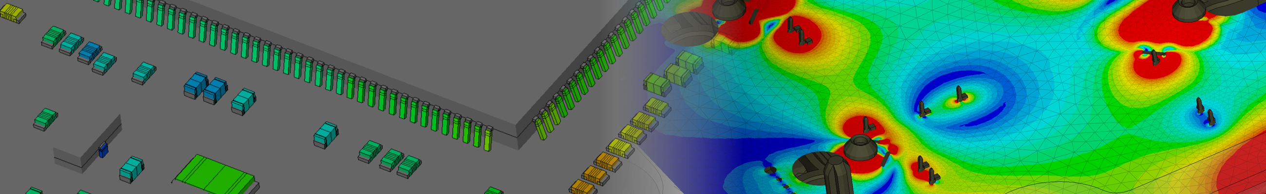
Vibration fatigue cracks in solder joints can lead to a malfunction or even short circuit in your PCBA and therefore to a damaged device. It is therefore crucial to ensure the mechanical integrity of all the solder joints of your product during its lifetime. Calculating the vibration fatigue of solder joints requires a very detailed model of each solder joint. FEMFAT MELCOM uses a large library of SMDs as well as different sub-structuring and sub-modelling approaches to calculate the vibration fatigue of all solder-joints on your PCB with FEMFAT.
It does so by automatically reading the ODB++ and Pick&Place data and creating an ABAQUS model of the whole PCBA. This model is used to conduct a modal analysis followed by a frequency response analysis.
With these results a FEMFAT job for every solder-joint can be generated and automatically calculated.
Therefore, critical areas on your PCBA can be identified and corrective measures can be set.
During the mounting process your PCB is deformed due to the tolerances of its mounting points, which can cause cracks in brittle components like MLCCs (Multi Layer Ceramic Capacitors). FEMFAT MELCOM can calculate PCB strains during the assembly process using two approaches. The worst-case approach calculates the worst possible occurring strain regardless of the probability of occurrence. Second the statistical approach calculates the PCB strains in relation to the probability distribution.
This process can help to optimize component positioning and finding mounting points including required stress reliefs.
PCBAs consist of SMDs, solder joints, traces, vias and isolating material which leads to complex and inhomogeneous structure. Due to the significantly different thermal expansion coefficients of the involved materials, even small temperature changes can lead to large thermal stresses. This can result in cracks, especially in the through-holes of the printed circuit board and solder joints. FEMFAT MELCOM assists the user by creating a suitable PCB model for the needed simulation task. After reading the ODB++ data it can automatically create a detailed model of the PCB (including all layers traces, vias) in the area of interest and reduce the model size of the remaining PCB by using our homogenization approach.